Teaching · Lee C. Zhao, MD
How robotic surgery works
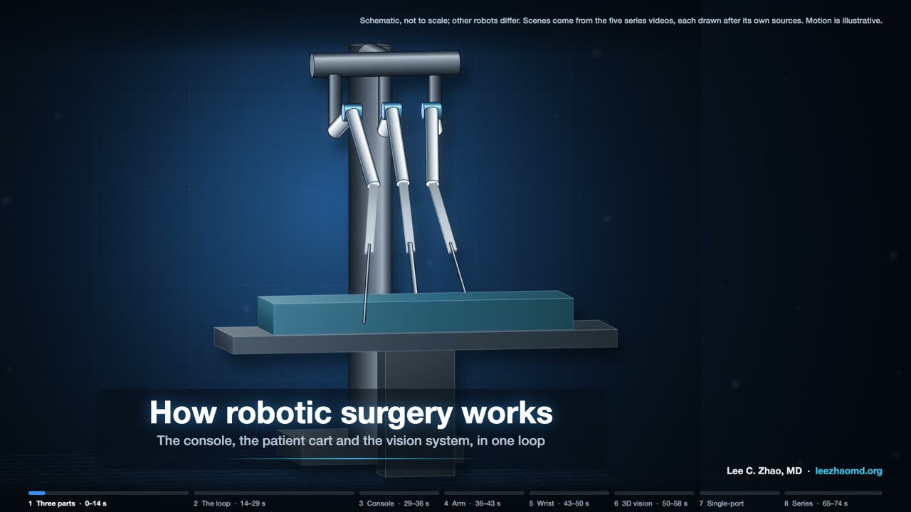
Six short videos follow one loop. The surgeon's hands move the controls at a console, the arm and instrument move in the patient, and a camera sends the picture back to the surgeon's eyes.
Every instrument motion starts as a hand motion. The first video shows the whole loop. Videos 2 to 5 take one part each, in the order the signal travels: console, arm, instrument, camera. Video 6 shows a system that passes a camera and three instruments through one port.
The videos are schematic and silent. Each follows one documented design, drawn from the patents, open research-kit documentation and papers listed under it. No video shows a specific product, and other robots differ. The platforms themselves, by origin, year and status, are on a separate page: Surgical robotics, worldwide.
Video 1 of 6 · 74 s
The whole loop
Key points
- The documented first-generation system comes as three units: the surgeon console, the patient cart and a video tower. The video treats the tower (light source, camera control units), the stereo endoscope on the cart and the viewer in the console as one vision system, because together they capture, process and display the picture.
- The surgeon sits at the console, away from the patient and usually in the same operating room. The console has a viewer, two hand controllers, foot pedals and an armrest. The cart holds the arms for the camera and the instruments.
- One pass of the loop: the hands move the controllers, a sensor on each joint reads its angle, and the control system moves the arm and instrument to follow. The endoscope's two images go to the viewer, one for each eye, so the surgeon sees each instrument move as the hands move it.
- Setup joints place each arm so that its remote center of motion sits at the port. The arm then pivots the instrument about that point.
Sources
- US 6,424,885 B1. Camera referenced control in a minimally invasive surgical apparatus. Priority 1999-04-07.
- US 6,720,988 B1. Stereo imaging system and method for use in telerobotic systems. Priority 1998-12-08.
- US 6,451,027 B1. Devices and methods for moving an image capture device in telesurgical systems. Priority 1998-12-16.
- Wang Y, Gondokaryono R, Munawar A, Fischer GS. arXiv:1902.10875. 2019.
- Lanfranco AR, Castellanos AE, Desai JP, Meyers WC. Robotic surgery: a current perspective. Ann Surg. 2004;239(1):14–21.
- Research-kit documentation, Johns Hopkins University: first-generation introduction and setup joints. dvrk.readthedocs.io.
Video 2 of 6 · 88 s
The surgeon console

Key points
- Each hand controller has a jointed arm and a four-joint wrist. Mostly, the arm sets position and the wrist sets orientation. Two levers make the grip. A sensor on each joint reads its angle, and a Hall-effect sensor reads the grip.
- The viewer has a separate display for each eye. A head sensor checks that the surgeon is at the viewer; if no one is there, teleoperation is not enabled. Presence is necessary but not sufficient.
- With a hand-held laparoscopic tool, the tip moves opposite the hand, because the port is a pivot. At the console, the control system compares the hand in the eye's frame with the tip in the camera's frame, so the tip moves on screen the way the hand moves. When the camera moves, the hand-to-tip mapping follows the new view.
- One documented pedal tray has five pedals: clutch, camera, focus, and monopolar and bipolar cautery. The clutch lets the hands reposition while the instruments hold still.
- Motion scaling turns large hand moves into small tip moves; one patent's example is 1 inch at the hand to 1/5 inch at the tip. A filter separates hand tremor from the signal before it reaches the instrument.
Sources
- US 6,424,885 B1. Camera referenced control in a minimally invasive surgical apparatus. Priority 1999-04-07.
- US 6,714,839 B2. Master having redundant degrees of freedom. Filed 1999-09-17.
- US 6,720,988 B1. Stereo imaging system and method for use in telerobotic systems. Priority 1998-12-08.
- Lanfranco AR, Castellanos AE, Desai JP, Meyers WC. Robotic surgery: a current perspective. Ann Surg. 2004;239(1):14–21.
- Research-kit documentation, Johns Hopkins University: hand controllers, teleoperation, foot pedals and head sensor. dvrk.readthedocs.io.
Video 3 of 6 · 89 s
The patient-side arm
Key points
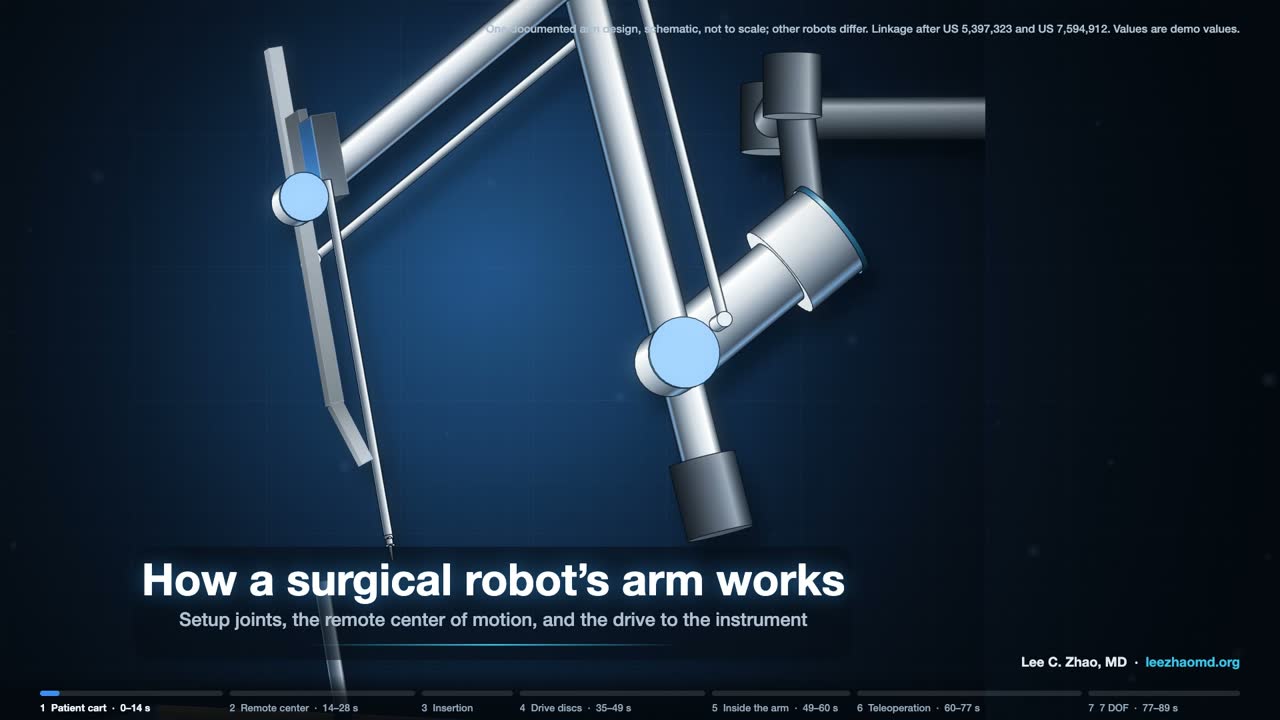
- Setup joints are moved by hand with their brakes released, then locked for the operation. They place the arm so that its remote center of motion sits at the port. A dark band on the cannula marks its approximate position.
- The arm pivots the shaft about that fixed point. Outer pitch and outer yaw rotate about it. A parallelogram linkage keeps the shaft aimed at it; in the documented arm, one motor drives the whole linkage. Some arms use belts instead of bars.
- For insertion, a carriage slides the instrument along a rail. The tip goes deeper; the remote center stays fixed.
- The carriage has four drive discs, each with two pins. A sterile adapter in the drape sits between arm and instrument, and the discs turn back and forth until their pins engage.
- With most instruments the chain has seven degrees of freedom: three from the arm (outer pitch, outer yaw and insertion) and four from the instrument (roll, wrist pitch, wrist yaw and grip).
Sources
- US 5,397,323 A. Remote center-of-motion robot for surgery. Filed 1992-10-30.
- US 6,246,200 B1. Manipulator positioning linkage for robotic surgery. Priority 1998-08-04.
- US 7,594,912 B2. Offset remote center manipulator for robotic surgery. Priority 1999-09-17.
- US 7,666,191 B2. Robotic surgical system with sterile surgical adaptor. Priority 1996-12-12.
- Wang Y, Gondokaryono R, Munawar A, Fischer GS. arXiv:1902.10875. 2019.
- Research-kit documentation, Johns Hopkins University: patient-side arms, setup joints and instruments. dvrk.readthedocs.io.
Video 4 of 6 · 80 s
The wristed instrument
Key points
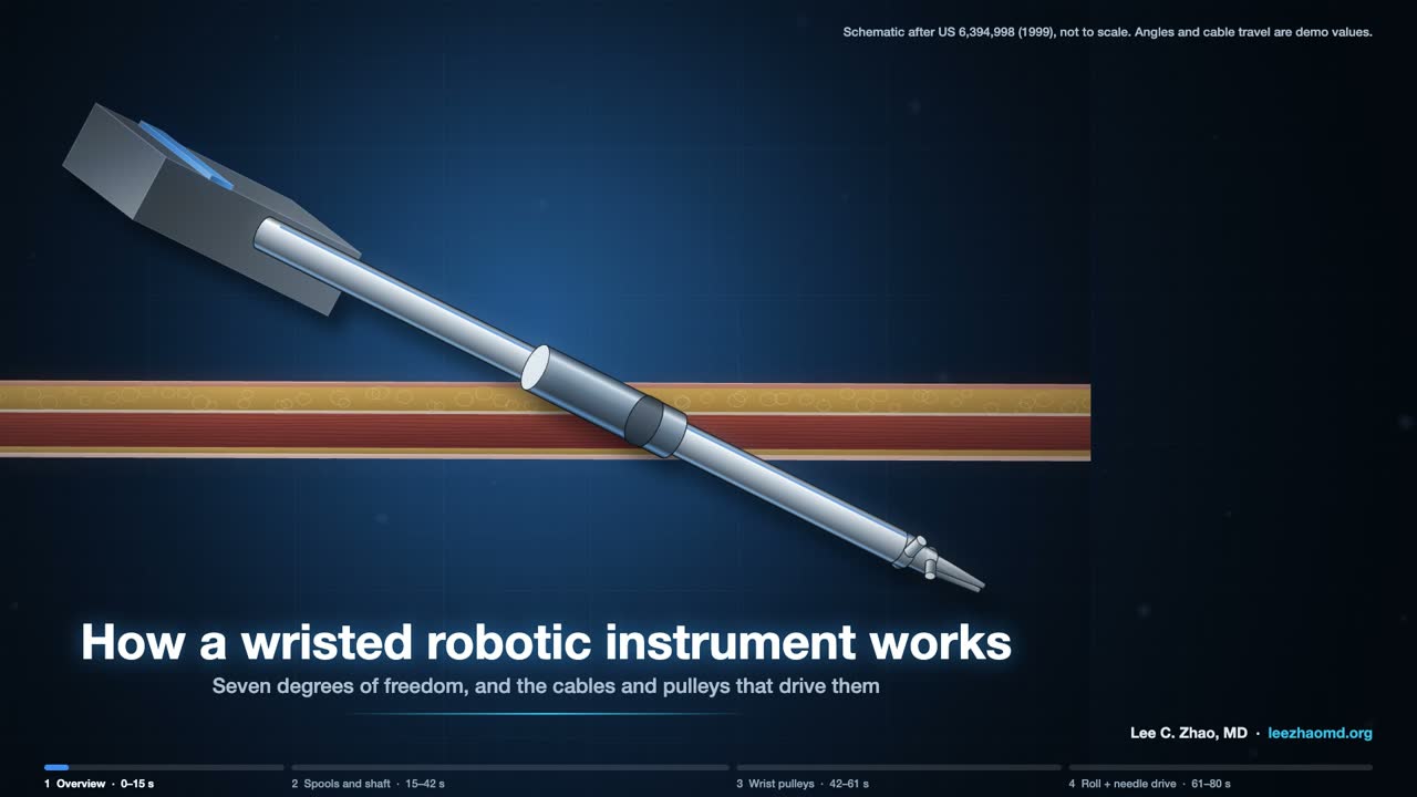
- Four discs on the back of the instrument take motion from the arm. In the 1999 patent the video follows, each disc turns a spool: roll, pitch, jaw 1 and jaw 2. Newer instruments roll the shaft with a gear.
- Cables carry the motion down the shaft. Along its straight run, rigid hypotubes take the place of cable.
- The pitch cables are anchored in the wrist link and pivot it. Each jaw cable loop runs over the wrist pulleys to its own jaw. Turn both jaw loops the same way and the jaws swing together: yaw. Turn them opposite ways and the jaws open or close: grip.
- Because the jaw cables ride the pulleys on the pitch axis, a pure pitch move needs both jaw spools to turn as well, or the jaws would swing. The research kit writes this as a coupling matrix between motor angles and joint angles.
Step by step: the wristed instrument in five clips
A wristed robotic instrument is a cable machine. Motors in the robot's arm turn discs on the back of the instrument. The discs wind cables, the cables run down the shaft, and the cables turn pulleys at the wrist. In the systems shown here, no motor goes into the patient.
Seven degrees of freedom
Seven motions reach the tip of a multiport instrument. Three come from the arm, which holds the shaft so that it pivots about a fixed point at the port: outer pitch, outer yaw, and insertion. In the research version of the system, the first two joints form that remote center of motion through a double four-bar linkage, and the third is a prismatic stage that slides the instrument through it (Wang et al., 2019). Four come from the instrument: roll of the shaft, wrist pitch, wrist yaw, and grip.
Four discs, four cable loops
The back of the instrument carries four discs that mate with the arm's actuators through a sterile adapter (research-kit documentation). In the 1999 patent the animation follows (US 6,394,998), each disc turns a spool. The roll spool turns a drum on the shaft through a pair of cables; the research-kit documentation notes that newer instruments roll the shaft with a gear instead. The pitch spool runs a cable pair over idler pulleys into the shaft. The two jaw spools each drive one jaw through its own loop.
Down the shaft
The cables are tungsten or stainless steel where they bend over pulleys. Along the straight run of the shaft, rigid hypotubes take the place of cable so the transmission does not stretch (US 6,394,998).
Pitch, yaw and grip
At the wrist, the pitch cables are anchored in the wrist link and pivot it. Each jaw loop wraps its own jaw pulley. Move both jaw loops the same way and the jaws swing together: yaw. Move them in opposite directions and the jaws open or close: grip.
This is worth pausing on, because the jaw cables also ride over pulleys on the pitch axis. Pitch the wrist and the jaw cable paths change with it. A pure pitch move therefore needs both jaw spools to turn as well, or the jaws would swing. The research kit writes this as a coupling matrix between motor angles and joint angles (Wang et al., 2019), and the animation uses the same ratio.
Driving a needle
Roll alone turns the needle about the shaft axis. That is the right circle only when the needle's center sits on the axis, and once the wrist is angled it does not. Driving a curved needle along its own arc takes the arm and wrist joints moving with roll: in the animation, six of the seven joints move during the drive.
Sources
- US 6,394,998 B1. Surgical tools for use in minimally invasive telesurgical applications. Priority 1999-01-22.
- Wang Y, Gondokaryono R, Munawar A, Fischer GS. arXiv:1902.10875. 2019.
- Research-kit documentation, Johns Hopkins University: instruments. dvrk.readthedocs.io.
Video 5 of 6 · 85 s
3D vision
Key points
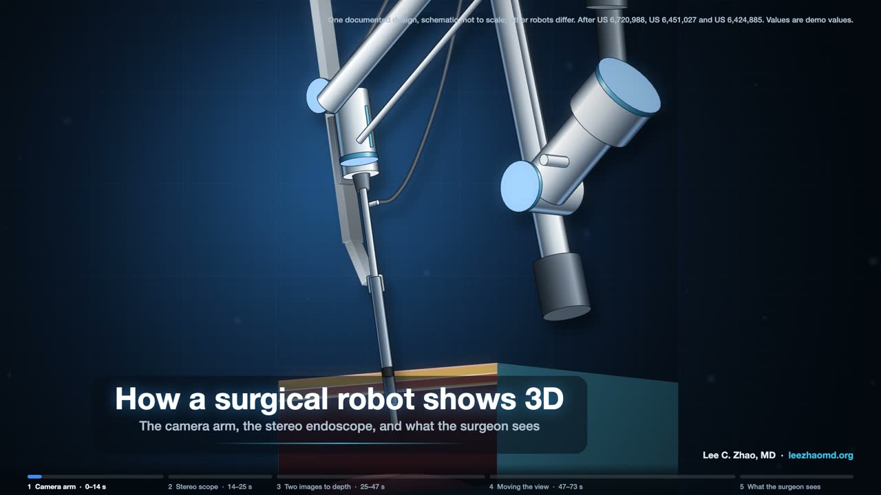
- A separate camera arm holds the stereo endoscope. Like the instrument arms, it pivots about a remote center at the port, with four motorized joints: pitch, yaw, insertion and roll. One documented design offered straight scopes and scopes angled 30°, up or down.
- The endoscope has two optical channels, left and right. Each carries its own image to its own camera, and two camera control units process the left and right video. In this design the cameras sit at the back of the scope; some designs put them at the tip.
- In the viewer, each eye sees only its own image, and the brain fuses the two into one view with depth. A single flat image gives depth only from cues such as shading, size and motion.
- To move the camera, the surgeon presses a foot pedal. Both hand controllers then move the view as if holding the scene, the instruments hold still, and the control system updates the hand-to-instrument map for the new view.
- In laparoscopy, 3D has not proved better than 2D for every procedure, and some surgeons have reduced stereo vision.
Sources
- US 6,720,988 B1. Stereo imaging system and method for use in telerobotic systems. Priority 1998-12-08.
- US 8,672,838 B2. Image capture unit in a surgical instrument. Filed 2011-08-12.
- US 6,451,027 B1. Devices and methods for moving an image capture device in telesurgical systems. Priority 1998-12-16.
- US 6,799,065 B1. Image shifting apparatus and method for a telerobotic system. Priority 1998-12-08.
- US 6,424,885 B1. Camera referenced control in a minimally invasive surgical apparatus. Priority 1999-04-07.
- Wong SW, Crowe P. Visualisation ergonomics and robotic surgery. J Robot Surg. 2023;17(5):1873–1878.
- Sinha RY, Raje SR, Rao GA. Three-dimensional laparoscopy: principles and practice. J Minim Access Surg. 2017;13(3):165–169.
- Research-kit documentation, Johns Hopkins University: camera arm, camera teleoperation and video. dvrk.readthedocs.io.
Video 6 of 6 · 86 s
The single-port system
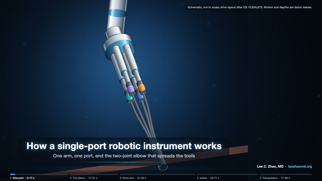
Key points
- One arm carries four instrument drives: one holds the camera and three hold 6 mm instruments. All four enter through one 25 mm cannula.
- Straight out of one port, the tools all point the same way. A two-joint elbow on each tool fixes that: the far joint bends by the same amount in the opposite direction, so the tip shifts sideways and keeps its direction. Each joint has two hinges at right angles, so the shift can go in any direction.
- Inside the elbow, actuation cables bend the near joint and coupling cables make the far joint bend back. Past the elbow, a snake-like wrist adds pitch and yaw, and a push-pull tendon down the center opens and closes the jaws. Rolling the shaft rolls the jaws; the wrist has no roll joint of its own.
- Elbows out, wrists in: the tips meet from two sides, which restores inside the body the triangulation that a single port takes away. The camera has its own elbow and wrist to aim at the tips.
- No public source I found describes how the commercial instrument's drive end turns disc rotation into cable motion. The video draws one patented layout and says so on screen.
Step by step: the single-port instrument in five clips
One port, four arms
A single-port system passes three 6 mm instruments and a camera through one 25 mm cannula (FDA 510(k) K173906; Orekhov et al., 2019). Straight out of one port, the tools all point the same way, which leaves nothing to triangulate with.
The two-joint elbow
Each instrument solves this with an elbow: two joints that bend by equal and opposite amounts, so the tip shifts sideways while keeping its direction (US 7,942,868; US 10,624,672). Each joint has two hinges at right angles, so the shift can go in any direction (US 7,942,868).
The drive end
How the commercial instrument's drive end turns disc rotation into cable motion is not in any public source I found. The animation draws one patented layout: discs turning capstans, idler pulleys, and levers that pull three cables per joint (US 9,839,439; US 10,076,348). Read it as one way the mechanism can be built, not as a teardown.
Inside the elbow and wrist
Inside the elbow, actuation cables bend the near joint, and coupling cables on both sides make the far joint bend back by the same amount (US 7,942,868). Past the elbow, a snake-like wrist adds pitch and yaw. A push-pull tendon runs down the center and through the wrist to open and close the jaws (US 10,932,867; US 10,076,348). Rolling the shaft rolls the tip; the wrists have no roll joint of their own (Orekhov et al., 2019).
Triangulation
Bend the elbows outward and the wrists back in, and the tips meet from two sides: the triangulation a single port takes away, rebuilt inside the body (manufacturer brochure, 2022). The camera has joints of its own, so it can look back at the working tips (FDA K173906; US 11,284,782).
Sources
- FDA 510(k) summary K173906. 2018.
- Orekhov AL, Abah C, Simaan N. Snake-like robots for minimally invasive, single port, and intraluminal surgeries. arXiv:1906.04852. 2019.
- Manufacturer single-port system brochure, PN1047732-US Rev A. 2022.
- US 10,624,672 B2. Surgical system instrument mounting. Priority 2010-05-14.
- US 7,942,868 B2. Surgical instrument with parallel motion mechanism. Priority 2006-06-13.
- US 9,839,439 B2. Rotary input lever gimbal. Priority 2013-08-15.
- US 10,076,348 B2. Rotary input for lever actuation. Priority 2013-08-15.
- US 10,932,867 B2. Reusable surgical instrument with single-use tip and integrated tip cover. Priority 2013-08-15.
- US 11,284,782 B2. System and method for multi-mode imaging device control. Priority 2008-06-27.
Limits of the videos
None of the videos is to scale. Angles, distances, cable travel and readouts are demonstration values. Each video follows one documented design, and current commercial systems differ in detail. Where a source shows a difference, as with the gear-driven roll or the belt-driven arm, the video notes it.